Thermal Fusion (Visible + Thermal Overlay)
infrared imaging project
Background
This project focuses on developing a low-cost, digital, infrared-visible-fusion platform.
During my time in the Navy, I became fascinated with the technology of infrared thermography. We used it to diagnose faulty equipment and to detect faults invisible to the naked eye before they became more severe.
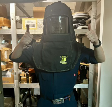
This often involved pulling the doors off of live 4160v switchboards while wearing fun gear like this to feel a little more secure.
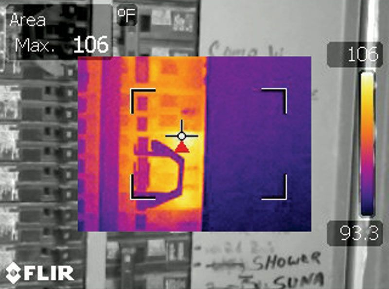
I used a variety of imagers during this time, most of them incorporating a combination of typical visible light cameras and of course infrared cameras.
The superimposition of the thermal image data ontop of visible data was valuable for evaluating a scene as a thermographer.
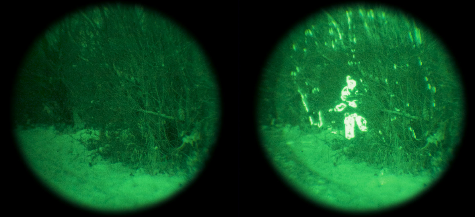
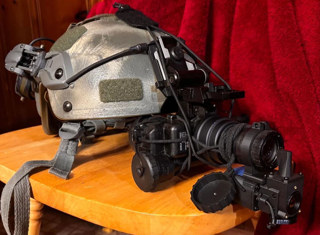
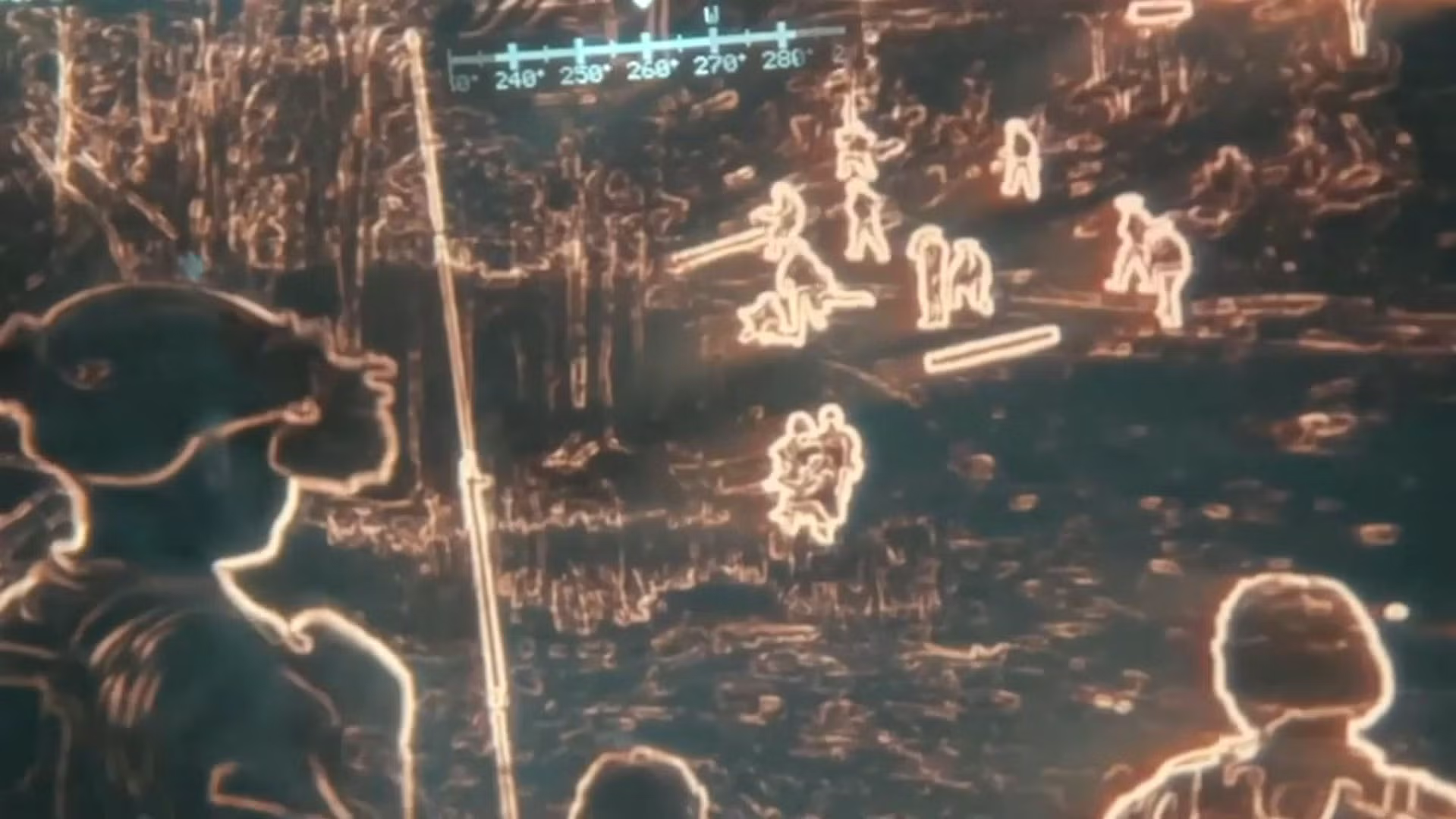
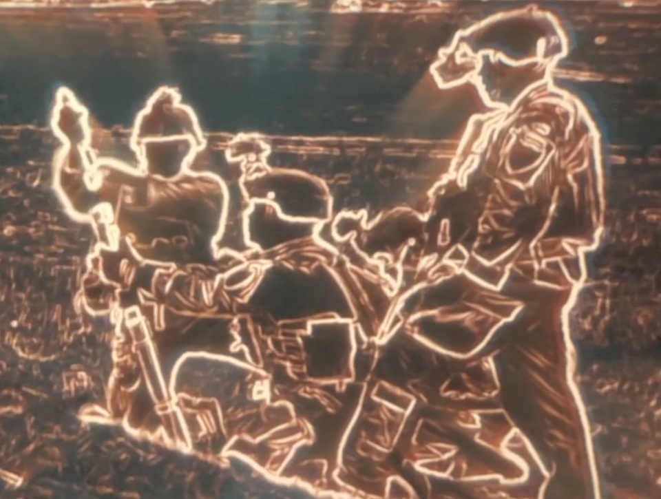
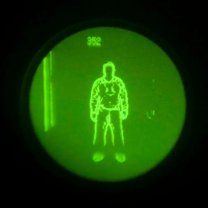
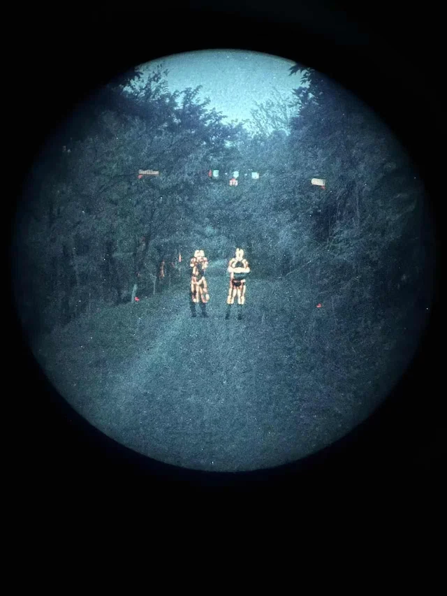
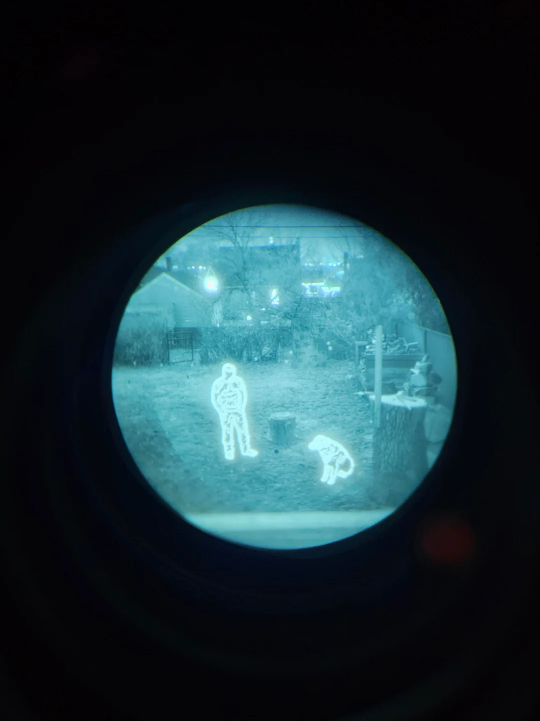
Around the same time, I was exposed to analog night vision technology. Although very effective on its own, the most advanced night vision being used in the field today involves overlay of a thermal camera feed over top of the night vision, pictured below.
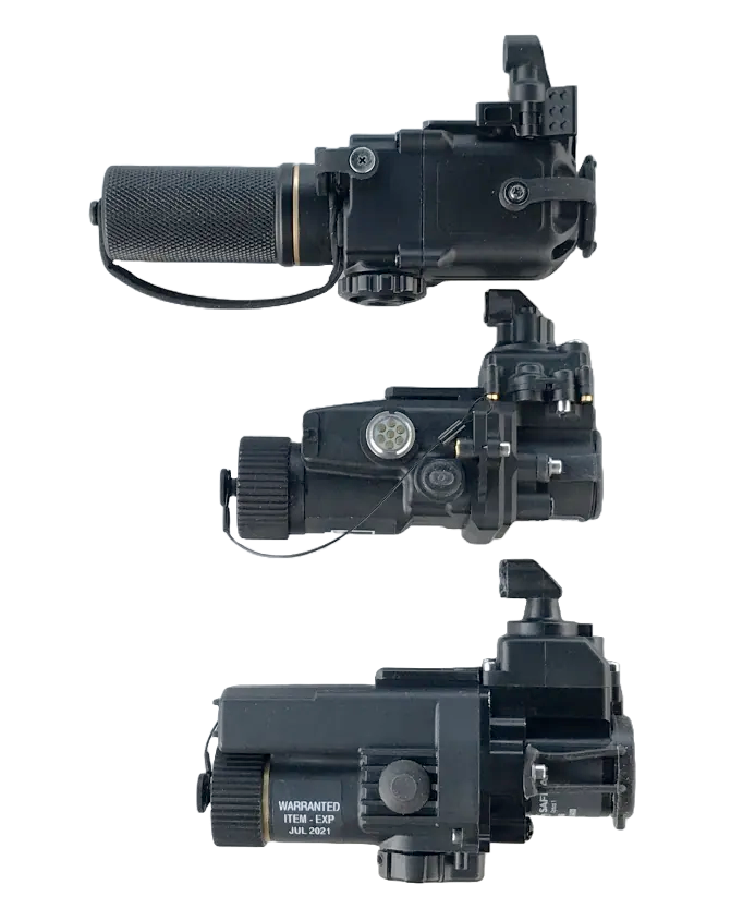
In their most common method of implementation, these overlays work by projecting the infrared image onto the input end of an image intensifier tube with a microdisplay. Almost all thermal fusion designed to be used on a helmet based solution achieves fusion this way, with a couple of unique exceptions. These are called clip on thermal imagers (or COTIS for short). Here are a few examples:
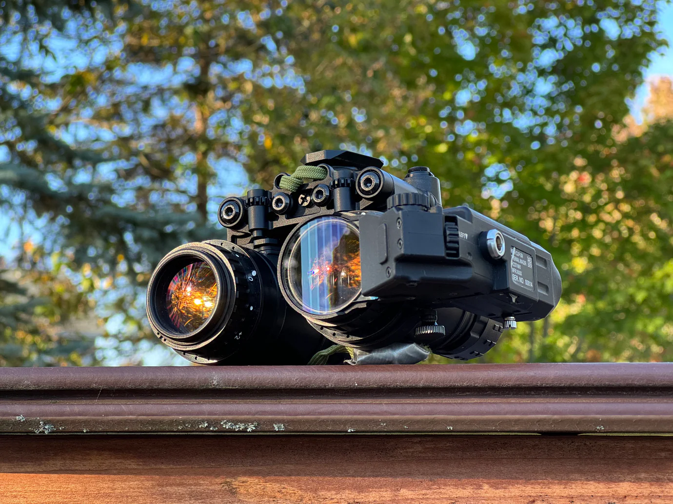
Exceptions include the RCOTI, which attempts to solve a major issue of the above examples: burn in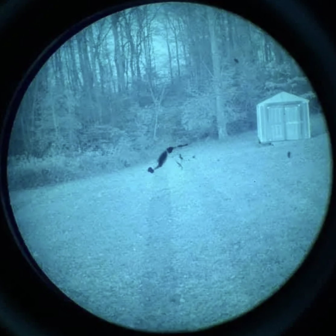 . As it turns out image intensifier tubes for analog night vision can degrade from intense light exposure. When the thermal image is aligned behind the lens instead of projected in front of it, this can be avoided.
The last few examples to note are state of the art, classified, or otherwise poorly documented.
In 2020 L3Harris won the contract for the Army's next generation of night vision technology. Among several new offerings is the ENVG-B. Shown below during the daytime (lol)
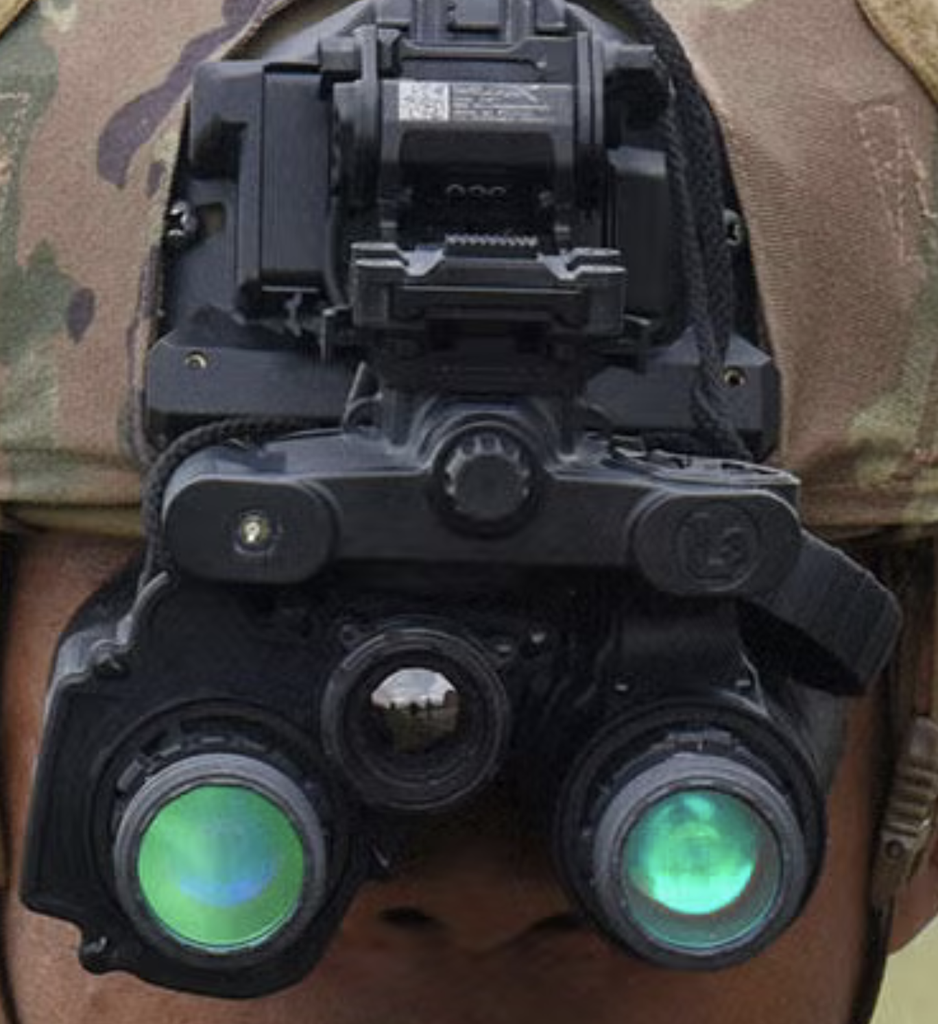
As we can see, it has no forward projection implement. Its image output is also drastically different from the examples given above.
Notably, L3Harris lists the right eyepiece as the AR-overlay lens and the left as a plain old intensifier tube, leading me to believe there is more going on under the hood than plain old projection. Although I would love to see more than a couple of stills to make a more informed inference, this tech is brand new and there is not much on the web about it. I suspect there is some sort of digital processing happening here in a specialized FPGA or other device.
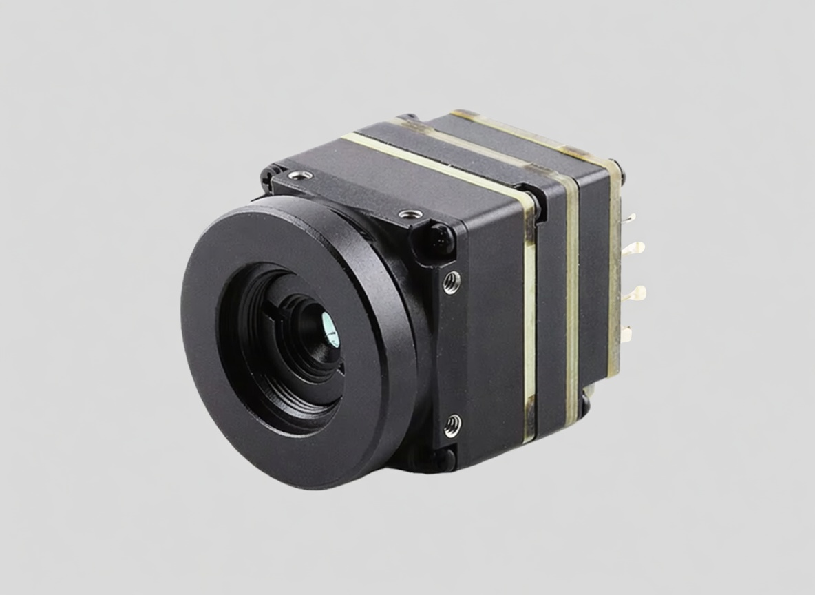
Among my general research into the technology of infrared imaging and microbolometry, I wanted to try my hand at achieving a similar effect. Although I cannot afford a set of night vision goggles or a high resolution off the shelf thermal imaging solution, I was able to acquire a low resolution 256x192 thermal sensor for ~$100 on Ebay and a wide FOV analog camera for ~$15. I did not know where to start, but I made it my goal to, at the very least, develop of a proof of concept, no matter how brutish. Below is what I was able to achieve given budgetary restrictions.
Design Constraints
Analog vs. Digital Video.
Both the thermal camera and the visible camera I have output a composite analog video output. There are two ways to go about thermal fusion, or for that matter, video in general:
- Analog
- Digital
Ideally, both signals would stay analog, and we could find some means of overlaying the thermal. There are several problems with this approach.
The first is that that composite video feed, transmitted over a single wire, consists of luminance, chrominance, and sync information all multiplexed together on the same signal. The sync information comes in the form of pulses from an crystal oscillator in each camera. Even if each camera was outputting the same frame rate (they are not), the two oscillators would likely never be perfectly in phase. This would result in the two feeds always being at a different point. Without deep diving too much into the complexities of the waveforms, the takeaway is that two composite video feeds need to be what is called "genlocked" - a process by which the two crystal oscillators sync pulses are made to be aligned. This is impractical.
The second problem is that by staying in the analogue domain, we leave off the table the option to modify either signal in any way.
Based on what I could dig up, this is impossible or extremely impractical without digital conversion.
Once in the digital domain, several additional constraints shape what is actually achievable with this hardware.
Resolution mismatch.
The thermal sensor is 256x192 pixels. The visible camera is 720x576. This is less notable than the next constraint, but still relevant later.
Field of view mismatch.
The visible camera has a 165 degree diagonal field of view (FOV) lens. The effective FOV of a microbolometer is a factor of many things, including pixel pitch, resolution, sensor size and focal length of the lens.
FOV calculations
After mathematically calculating the FOV values for the thermal camera, I suspected that either I was wrong in my math, or that the manufacturer specs weren't fully accurate. I wrote a quick script to measure the FOV digitally.
digital FOV measurement
| H FOV | V FOV | D FOV | |
|---|---|---|---|
| Published | 45.0° | 33.0° | 54.0° |
| Calculated | 42.8° | 32.5° | 53.6° |
| Measured | 40.8° | 31.2° | 49.9° |
In practice, this means the thermal only covers about a quarter of what the visible camera sees. This means the overlay is only a partial one, concentrated in the center of the frame.
Parallax.
The two cameras are physically separated from each other. At a minimum, constrained by the size of the cameras themselves, the distance between the lens centers is ~2cm. This leads to a further misalignment of the two images, which becomes less severe as the distance away from the cameras increases.
Fisheye distortion.
The 165 degree fisheye lens introduces heavy distortion. Straight lines appear curved, etc, etc. See image below.
Frame rate mismatch.
The thermal camera outputs at 25fps. The visible camera outputs at 60fps. This isn't too big of an issue and I don't suspect it will be noticeable.
Thermal Overlay Camera System
Hardware
Cameras:
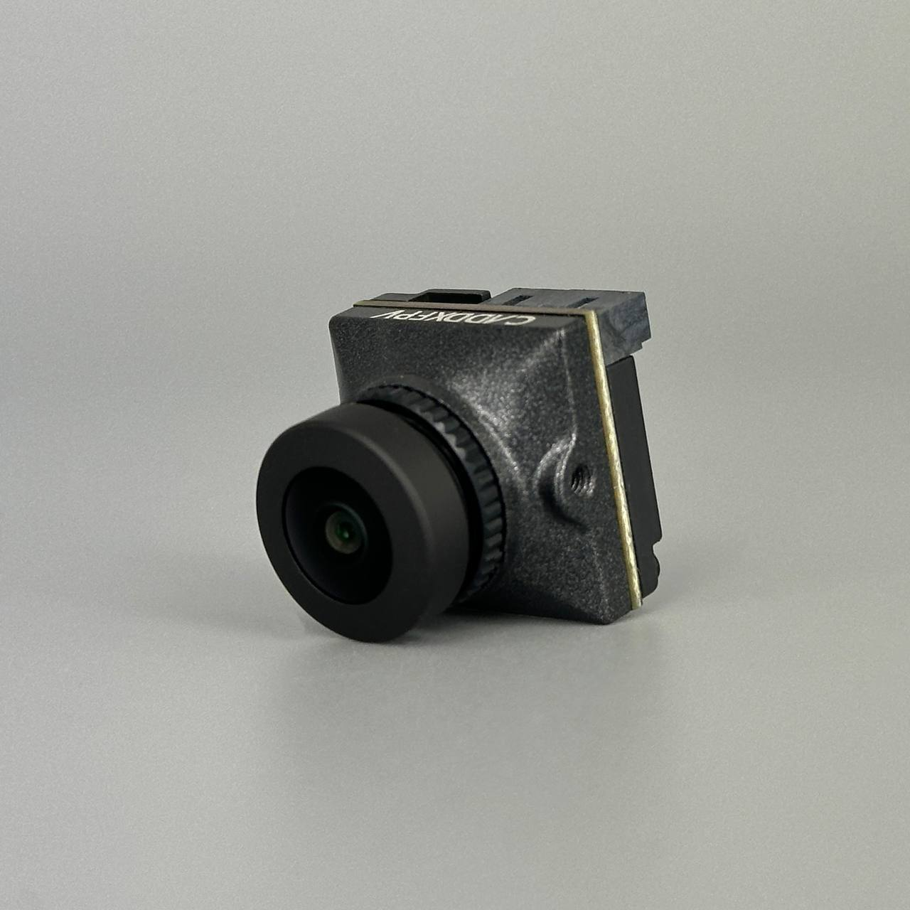
Both cameras are analog CVBS (composite video). The visible camera is a Caddx Ratel 2 with a 165-degree fisheye lens at 720x576 resolution. The thermal camera output is 256x192 pixels.
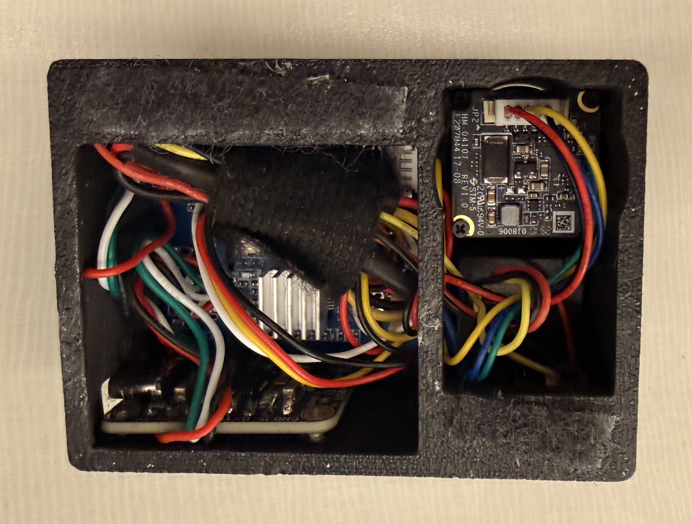
ADCs (Analog to Digital converters):
Analog video cannot go directly into a USB port. Each camera connects to a MS2107 chip, which digitizes the camera feed and serves it over 4 wire usb 1.0 standard.
USB Hub:
As I will later detail, initial experimentation was done on in python on Windows. As I began wanting to move the apparatus around between my pc and my macbook, it became inconvenient to constantly unplug and replug the usbs. I purchased an adafruit CH334F chip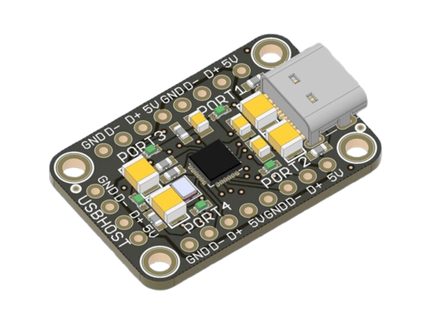 and hardwired the MS2107 outputs to it. This made the whole camera package alot smaller, because I was able to desolder the chunky usb 1.0 male ends from the ADCs and connect both cameras to a pc or rPi using a single usb c cable. For $5 at MicroCenter, this wasn't a bad price for this headache resolver.
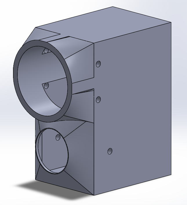
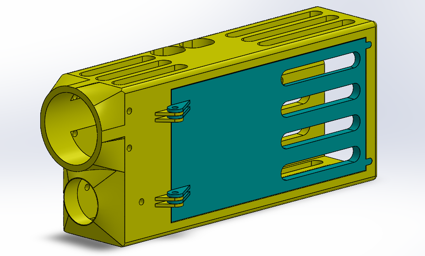
3D Printed Test Shell:
I mocked up a couple of shells for the hardware in Solidworks. This was similarly done mostly for ease of mobility.
-
Camera Cage: Other than some initial research, this camera cage was the first thing I did on this project. After a couple sets of measurements on camera fastener spacing to make sure I nailed it on the first go, the design went smoothly. The benefit of designing the camera cage first is that I can just reference all of this geometry in any future design.
- V1: worked all right but didn't interface well with my macbook. This was also designed to fit a raspberry pi zero 2 w. Eventually the goal will be get this whole pipeline to run on small device / specialized microcontroller, but I have a lot to learn before then. (Initial framerates on raspberry pi for an edge detection overlay were avg ~20fps and a couple hours of optimization attempts got me nowhere). This design featured plenty of ventilation for the hot running rPi a removeable door for quick access, and slots for the rPi's I/O.
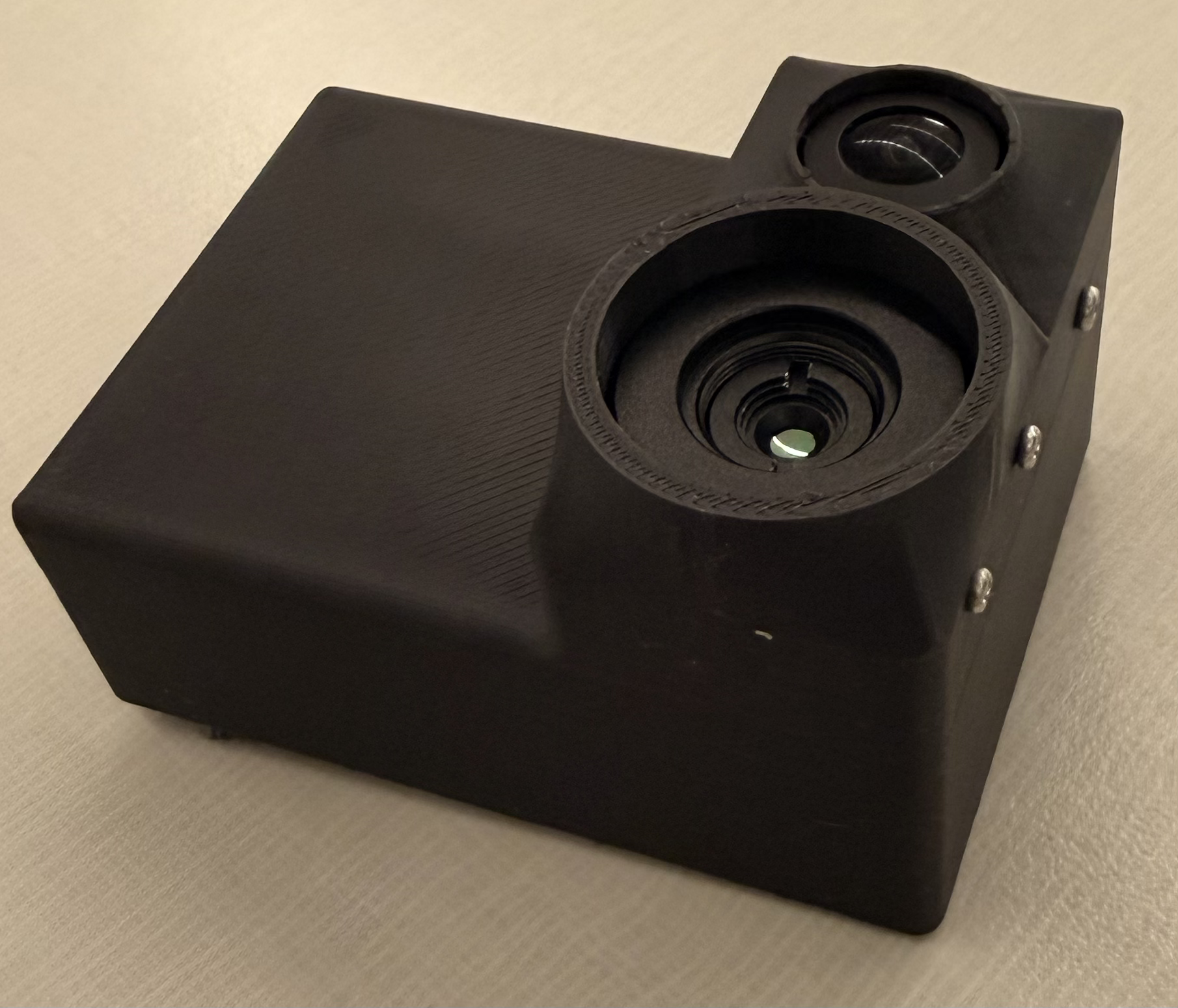
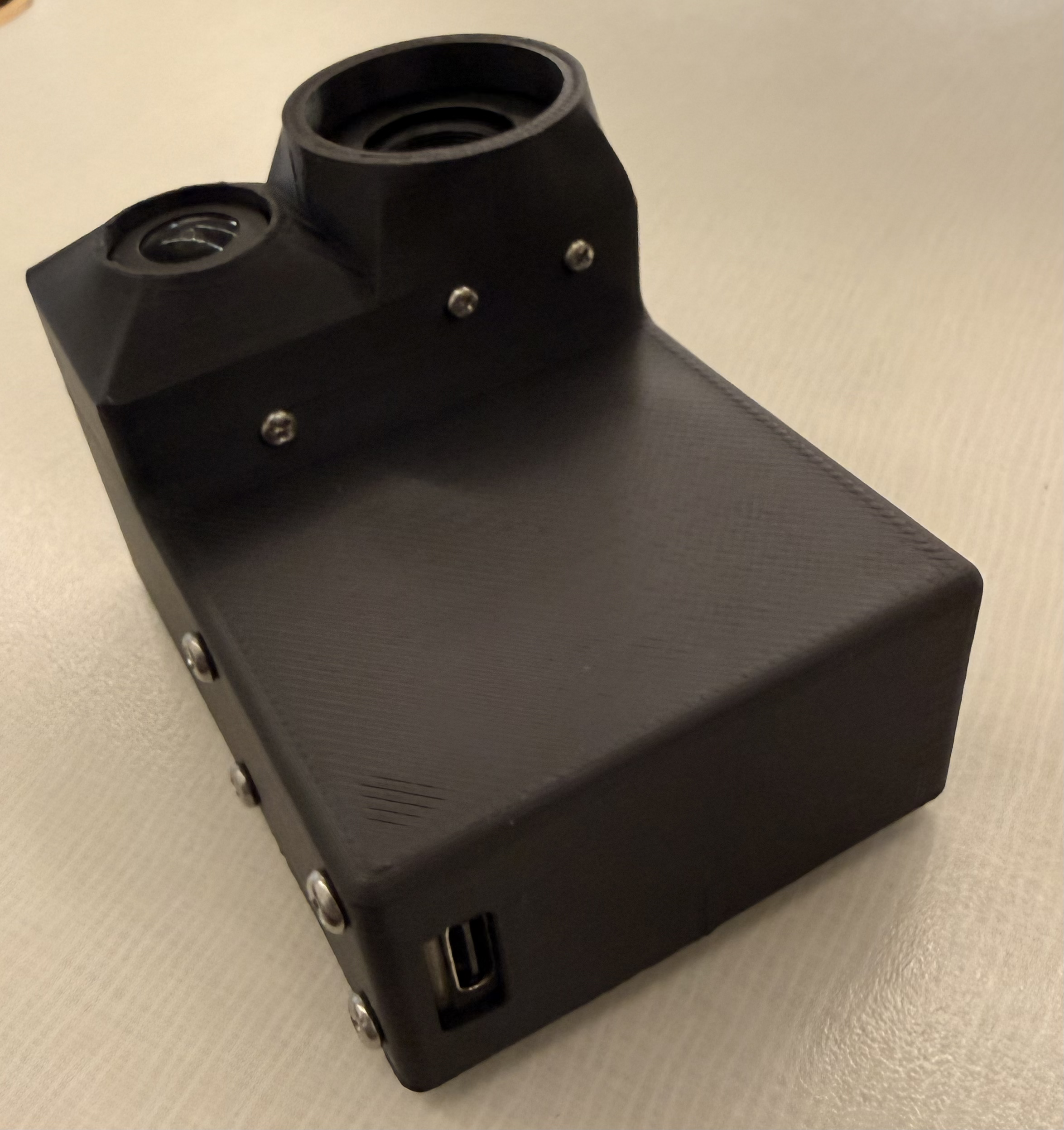
V1 shell - V2: designed to velcro on to the lid of my Macbook. It could probably do with a little bit of ventilation, but chip temps are comfy right now. In this design, the output is consolidated to a single usb-c. Very convenient indeed.
Software Approach
On Windows
I started the development on Windows. I had initially bought a cheap $7 capture card with standard av input and had no luck in getting either PAL camera feed to display on Windows. I do not recommend these capture cards. Ironically, the IC on both this faulty board and the final ADC board is a Macrosilicon MS2107, but for whatever reason this first capture card would not output any readable signal. Once I got the right hardware I got to work. I did some initial experimentation in OBS to get a feel for the differences in the cameras FOV and perspective warp between the two.
As I predicted, there is a lot left to be desired in this initial overlay.
I made a quick python venv with OpenCV for handling the cameras and got to work. In computer vision, homography is the process by which two images can be mapped on the same planar surface viewed from different angles or positions. OpenCV comes packed with features to enable simple implementation of this concept. In documentation and tutorials on the topic, the common method being used to map points from each image for projection was a high contrast checkerboard pattern. I thought about this. On the visible feed, an image of a checkerboard pattern would suffice, but on the thermal, I would need a checkerboard which provided thermal contrast. I muddled around looking for something to fashion a thermal checkerboard of sorts out of, until I found a square of 1mm thick steel from some old project. I laid out strips of electrical tape across it, and cut out a checkerboard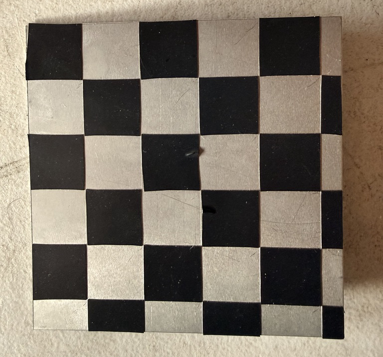 negative out of it. This was exactly what I needed, I thought. The metal contrasted with the electrical tape both thermally and visually.
After a couple hours of fiddling, I was unsatisfied with the results.
I decided to take a new, more manual approach, that required no specialized checkerboard and could be repeated anywhere for on the spot calibration. This new approach involved manually selecting similar known points on each image, and computing the projection based on this point array from each image. The results were immediately better.
On MacOS
I proceeded with the rest of the project on macOS. Although there were a couple of quirks to change around to get the cameras indexed and detectable, the rest of the work I had done for Windows carried over well.
Video Results
I developed 4 main scripts for this proof of concept.
First, a control overlay to allow us to visualize the effect of the fisheye lens on the two cameras' relative view.
The next is for homography. This point alignment script allows for manual selection of correlary points from each image feed, and stores the resultant array in a numpy array archive for later use.
The third script overlays the infrared output, applies the homography, and applies a different colormap than the default grayscale.
The video below shows the inferno overlays ability to detect latent heat from the dogs bed after he has left the frame.
A visualization of the effects of fisheye distortion and homographized overlay. The left figure shows the fisheye in pixel space with the world grid lines bent by the barrel distortion. The right shows the same scene with distortion removed and the world grid lines straightened. Both show the effects on the overlayed thermal in the center.
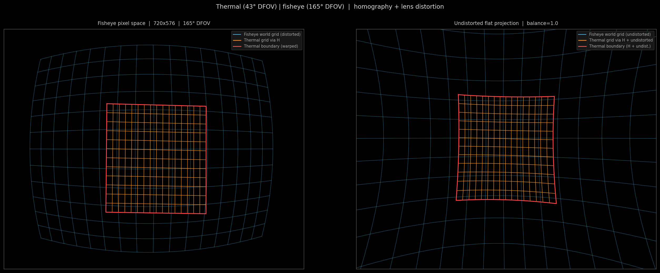
In practice, we wont be undistorting the fisheye effect, because this is what grants us the ultra wide field of view, but I thought it productive for understanding purposes to show the undistorted effects. The intrinsics and distortion of the lens were calculated using OpenCV's cv2.fisheye.calibrate() function and saved in an npz. The graphic was made with a combination of this lenscal.npz and our homography.npz from earlier.
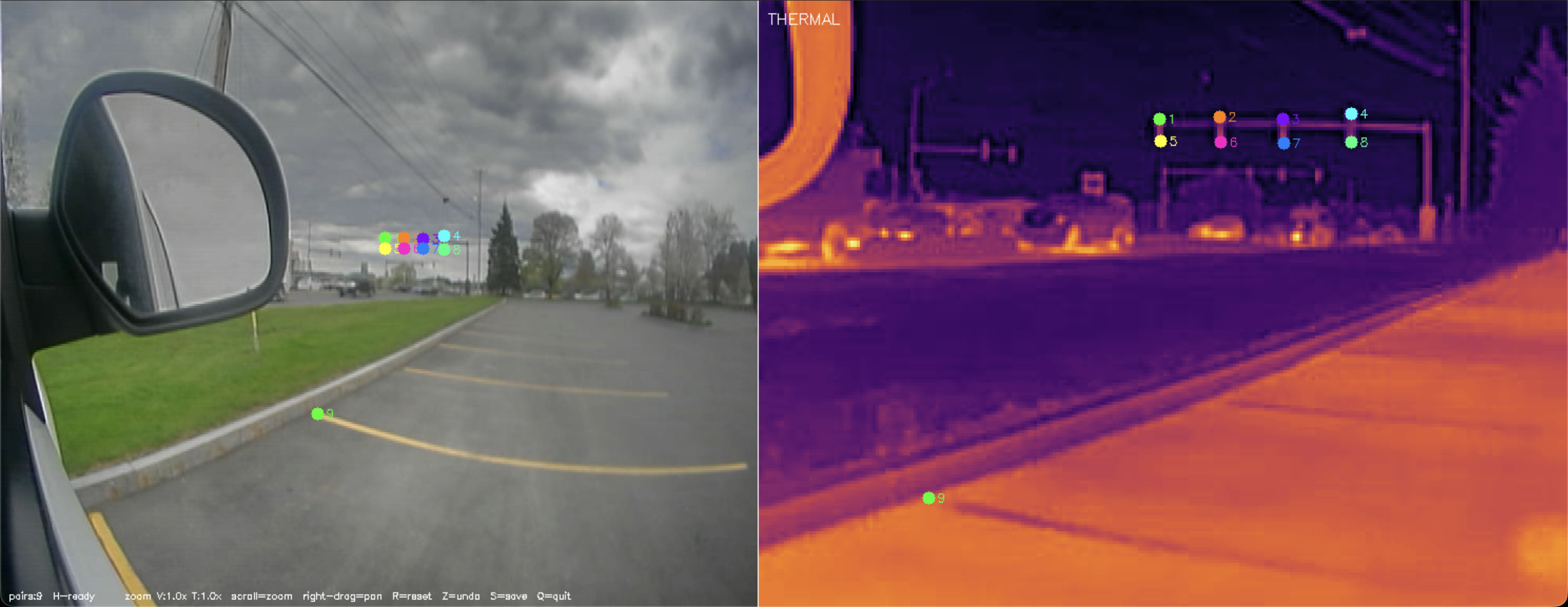
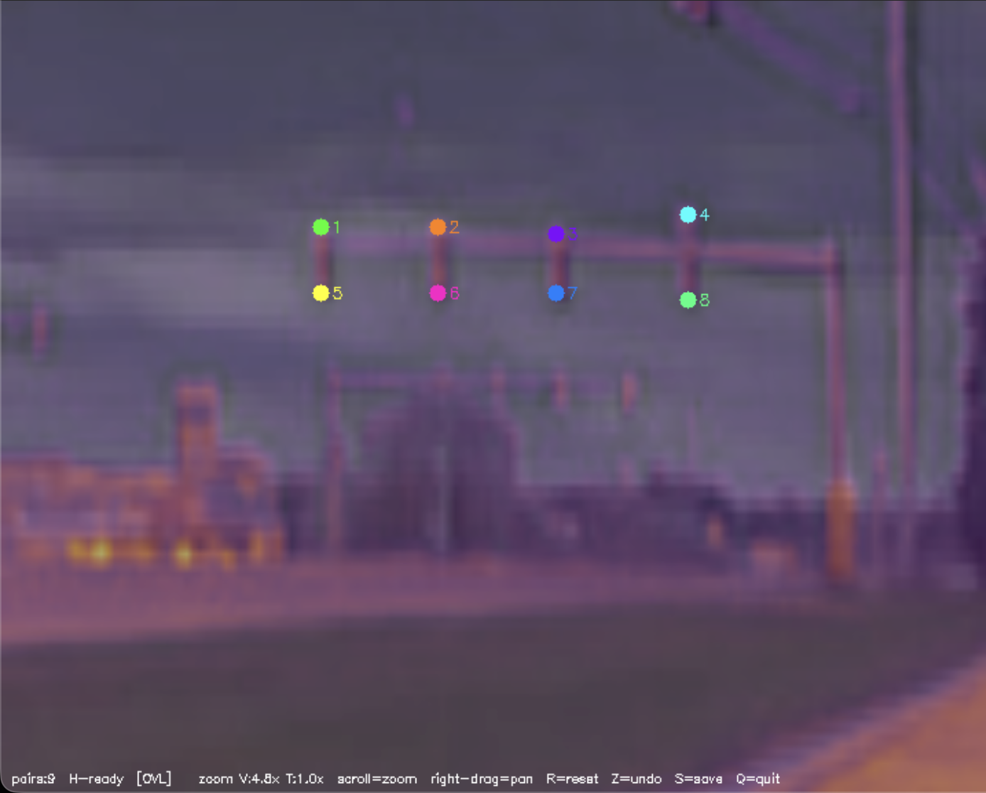
Point Alignment Workflow
Point alignment of only nine points yields a near perfect overlay. Shown below is the side by side comparison, followed by the overlay.
Deployment on rPi zero 2 W
Edge Detection
The final script is as close as I could achieve to an emulation of the few ENVG-B output images we have. It detects blobs of a certain area within certain threshold, and applies an edge overlay.
Future Plans
V2 with upgraded cams coming soon
Bill of Materials
| Component | Qty | Unit | Total |
|---|---|---|---|
| 256×192 Thermal Sensor | 1 | ~$100 | ~$100 |
| Caddx Ratel 2 (visible camera) | 1 | ~$15 | ~$15 |
| MS2107 ADC Board | 2 | $10 | $20 |
| CH334F USB Hub Chip | 1 | $5 | $5 |
| TOTAL | ~$140 | ||